| |
|
Initial Design condition -1 |
Optimized Design-2 |
30kW Added load to Check Life span DC & resilience
|
| Sr.No. |
Benchmarking parameter
|
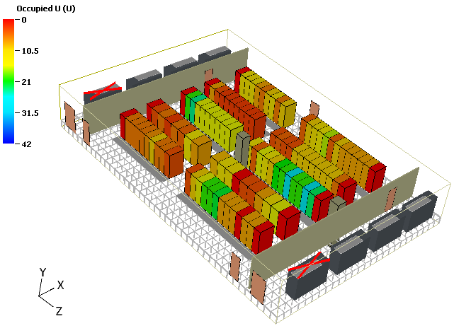
IT load 170kW + 6x22TR (77kWx6no’s cooling- 462kW)
|
IT load 170kW + 4x22TR (77kWx4no’s cooling- 308kW) |
IT load 200kW + 4x22TR (77kWx4no’s cooling- 308kW)
|
| 1 |
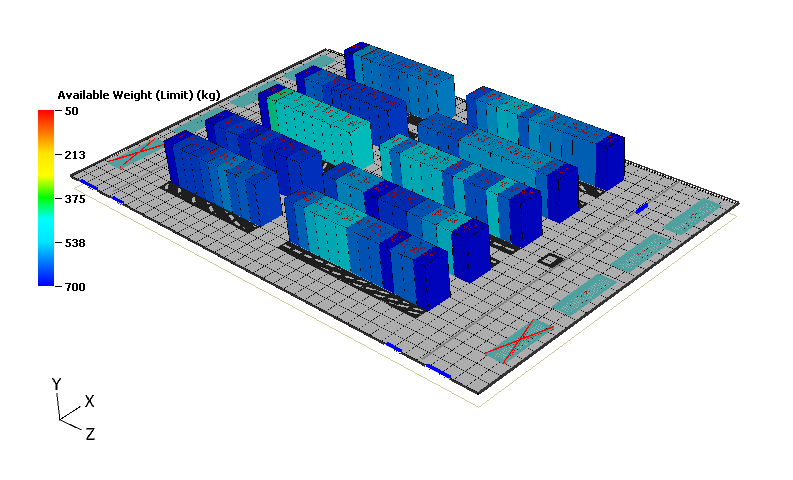
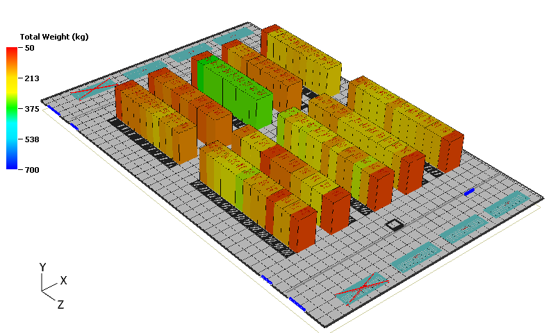
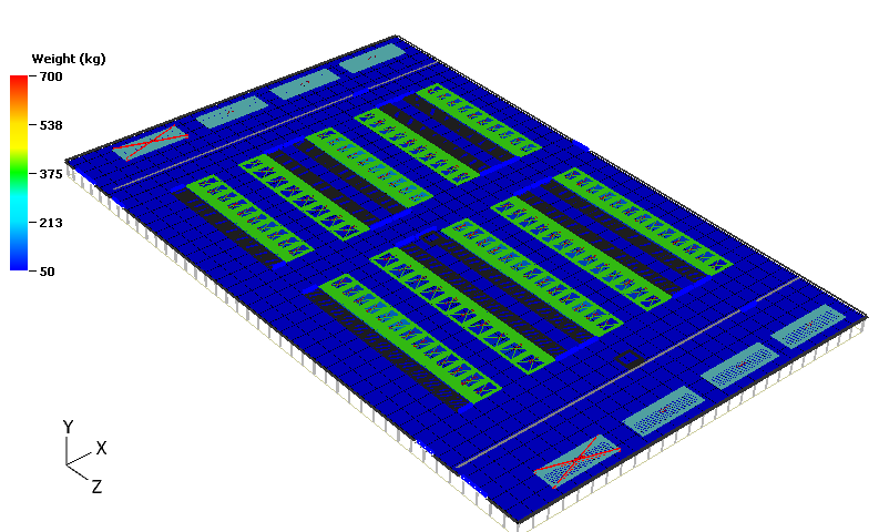
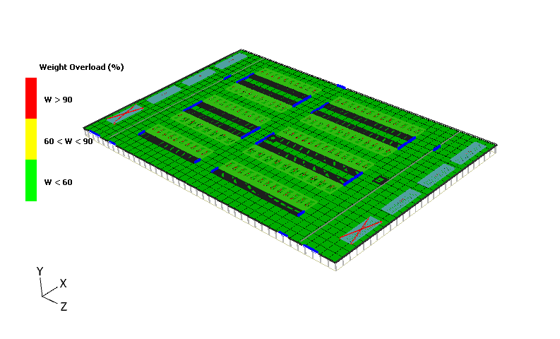
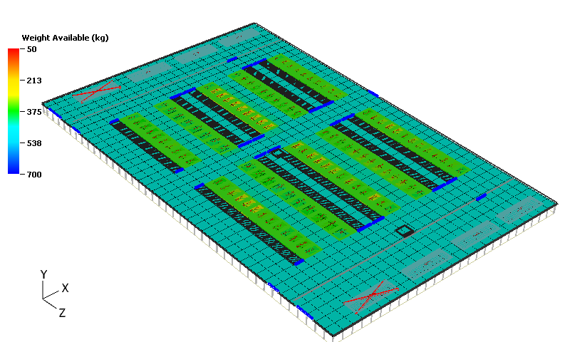
Weight analysis – Rack & Raised floor |
✔ |
✔ |
✔ |
| 2 |
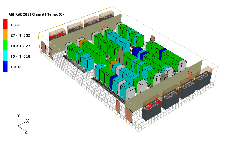
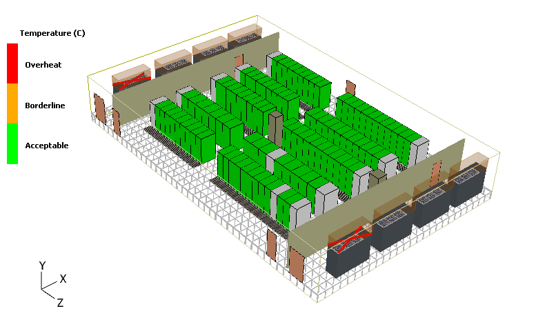
ASHRAE Limits |
✔ |
✔ |
✔ |
| 3 |
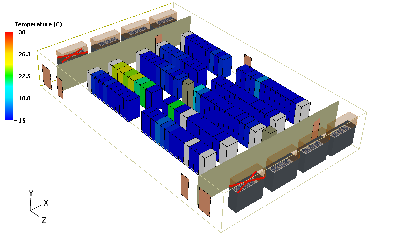
Over heat racks/Over cooling |
✔ |
✔ |
✔ |
| 4 |
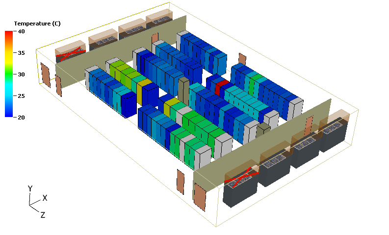
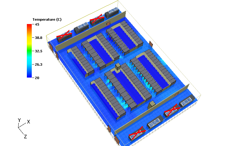
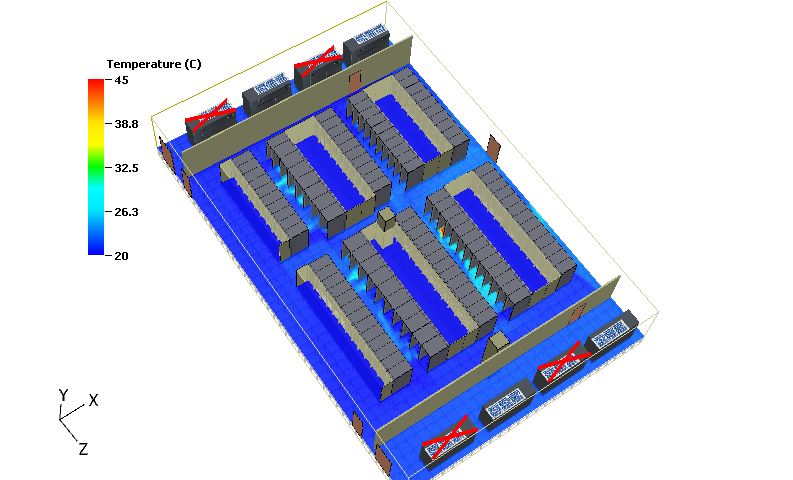
Rack intake & outlet temperature |
✔ |
✔ |
✔ |
| 5 |
Temp - Cabinet at Bottom ,Halfway, Top |
✔ |
✔ |
✔ |
| 6 |
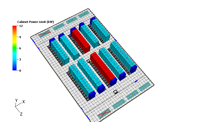
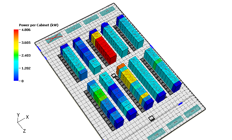
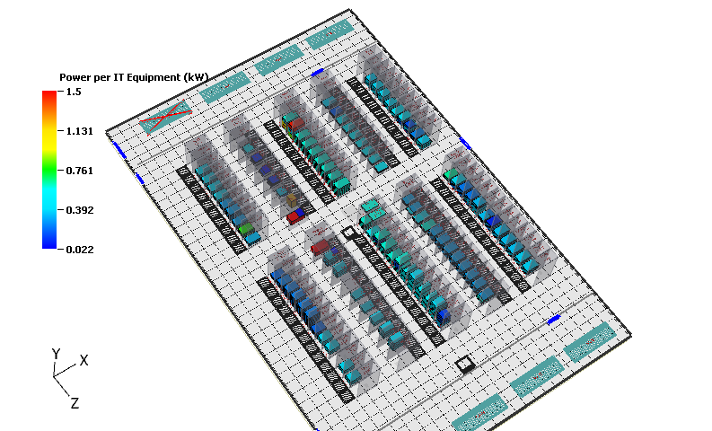
Rack power analysis |
✔ |
✔ |
✔ |
| 7 |
Cooling redundancy |
✔ |
✔ |
✔ |
| 8 |
CAPEX Savings |
❌ |
✔ |
✔ |
| 9 |
Opex savings |
❌ |
✔ |
✔ |
| 10 |
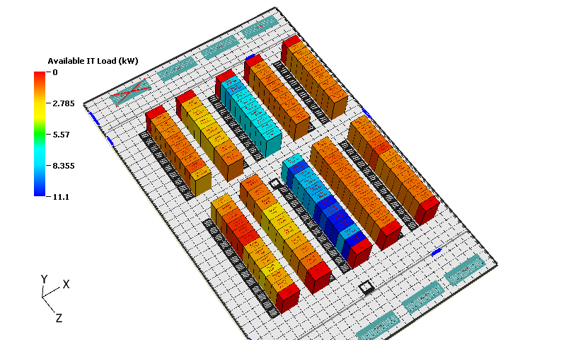
Absorb Future IT load |
✔ |
✔ |
✔ |
| |
Optimum Design Scenario |
❌ |
✔ |
✔ |